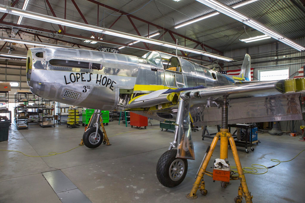
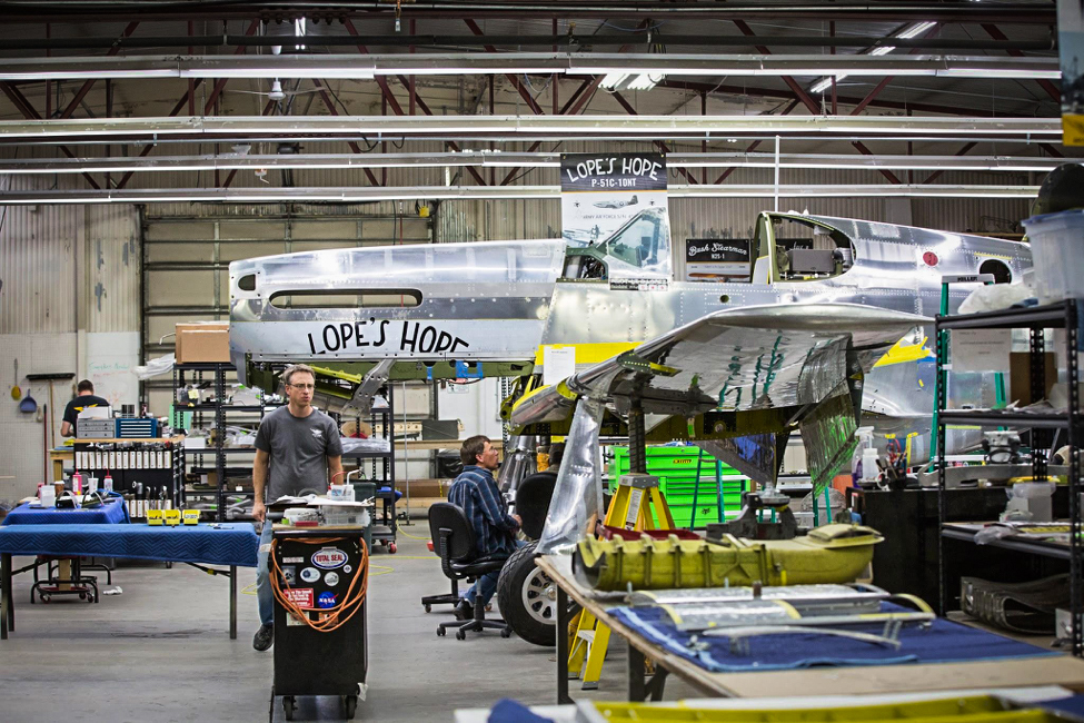
Lope's Hope is coming together. (photo via AirCorps Aviation)
Lope’s Hope is coming together very well indeed at AirCorps Aviation in Bemidji, Minnesota. (photo via AirCorps Aviation)
As many of our readers will know, WarbirdsNews is proud to have AirCorps Aviation as a sponsor. Their world-class aeronautical facility offers so much more than the traditional warbird shop … they are a one-stop shop for practically every aspect of warbird restoration from detailed historical research, to design to fabrication of the most complex and unique components. They focus on the details both large and small. We are a little behind in sharing what AirCorps Aviation has been up to of late, so we would like to catch you up on progress with their restoration of P-51C Mustang 43-24907… one of three rare WWII fighters currently under rebuild at their base in Bemidji, Minnesota.
So here is Chuck Craven’s restoration report for progress during June/July, 2017
The restoration is nearing completion as you will see in this month’s update. Many more visually interesting operations happen near the end, so this time there are many photos. We will begin with a visit by some special folks who made a trip to see Lope’s Hope 3rd and meet the restoration team and owners of this P-51C.
Distinguished Visitors
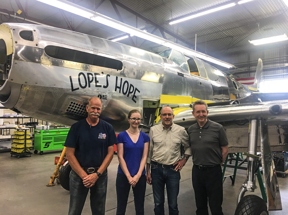
Donald Lopez’s son and granddaughter, Dr. Donald Lopez, Jr. and Laura Lopez, came all the way to AirCorps in Bemidji to take a look at the P-51C being restored in Donald’s honor. They were able to see another P-51, a “D” model, fly when Texas Flying Legends’ Bruce Eames and Warren Pietsch departed after the visit.
(L-R)Warren Pietsch of Texas Flying Legends Museum, Laura Lopez, Bruce Eames of Texas Flying Legends Museum, and Dr. Donald Lopez Jr. together in front of Lope’s Hope 3rd in the AirCorps restoration shop. (photo via AirCorps Aviation)
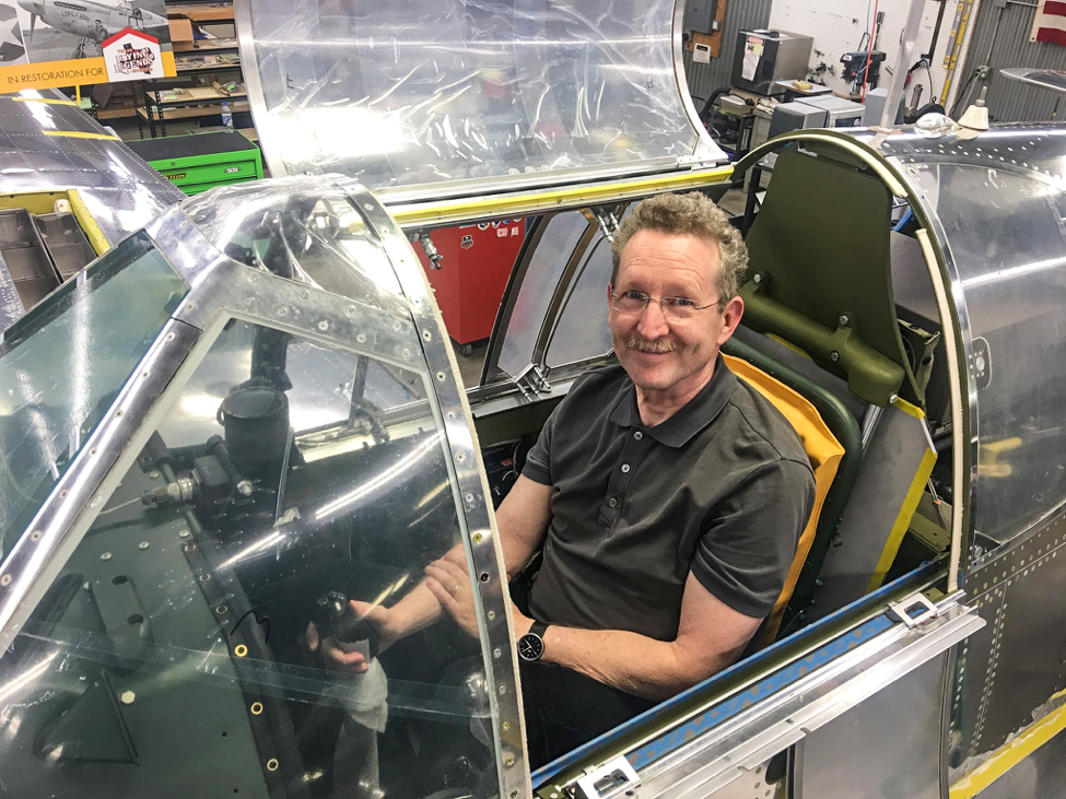
Dr. Lopez looks right at home in the P-51C! (photo via AirCorps Aviation)
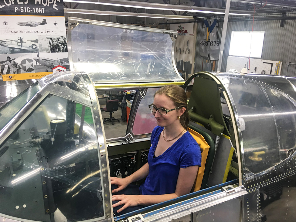
Laura experiences what her grandfather felt and saw in the cockpit of Lope’s Hope 3rd. (photo via AirCorps Aviation)
Cockpit
A great deal of ‘finish-work’ and equipment installation in the cockpit took place this month.
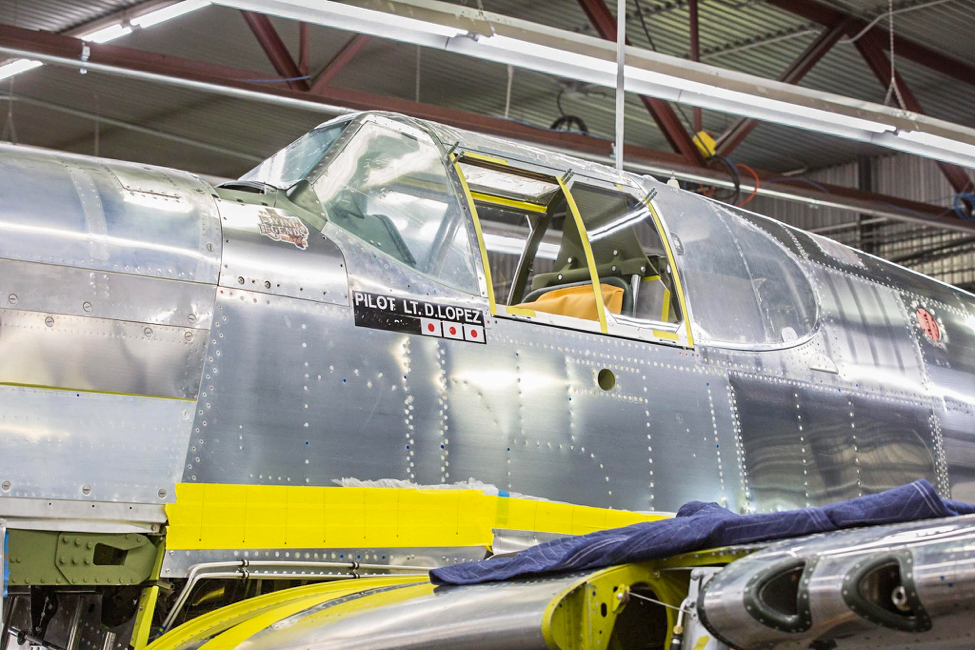
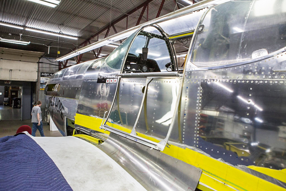
Exterior shot shows the pilot name and victory markings. (photo via AirCorps Aviation)
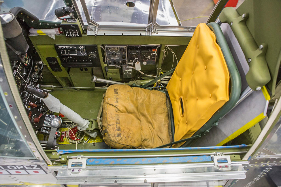
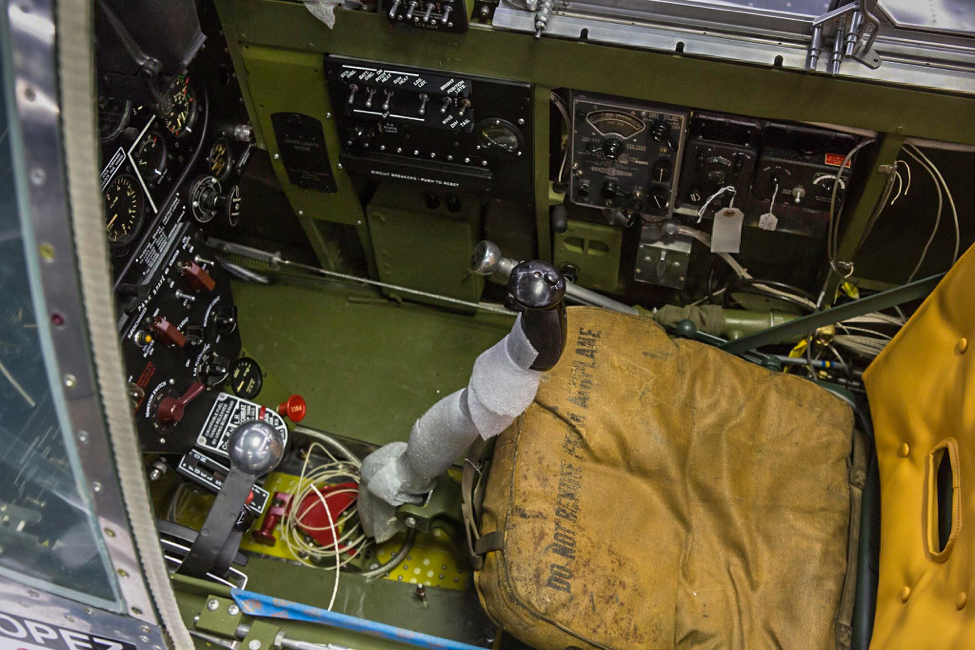
In this view of the seat and stick from above, you can see that there is still some wiring being done. (photo via AirCorps Aviation)
The button on the stick facing us is the bomb release button. (photo via AirCorps Aviation)
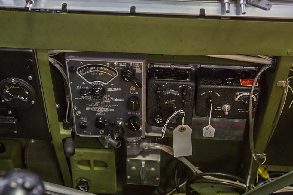
Lope’s Hope has a CBI-specific radio package. The three electronic boxes house, l-r, the MN-26 radio compass controller, the SCR 274 communications receiver, and transmitter. (photo via AirCorps Aviation)
The “D” window that encloses the radio compartment is visible here. Also barely visible is the fuel gauge for the fuselage tank. (photo via AirCorps Aviation)
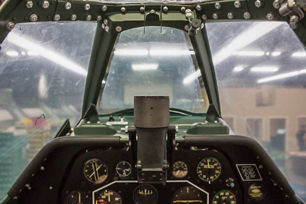
The top of the instrument panel showing the N3B gunsight – the reflector is still to be installed. (photo via AirCorps Aviation)
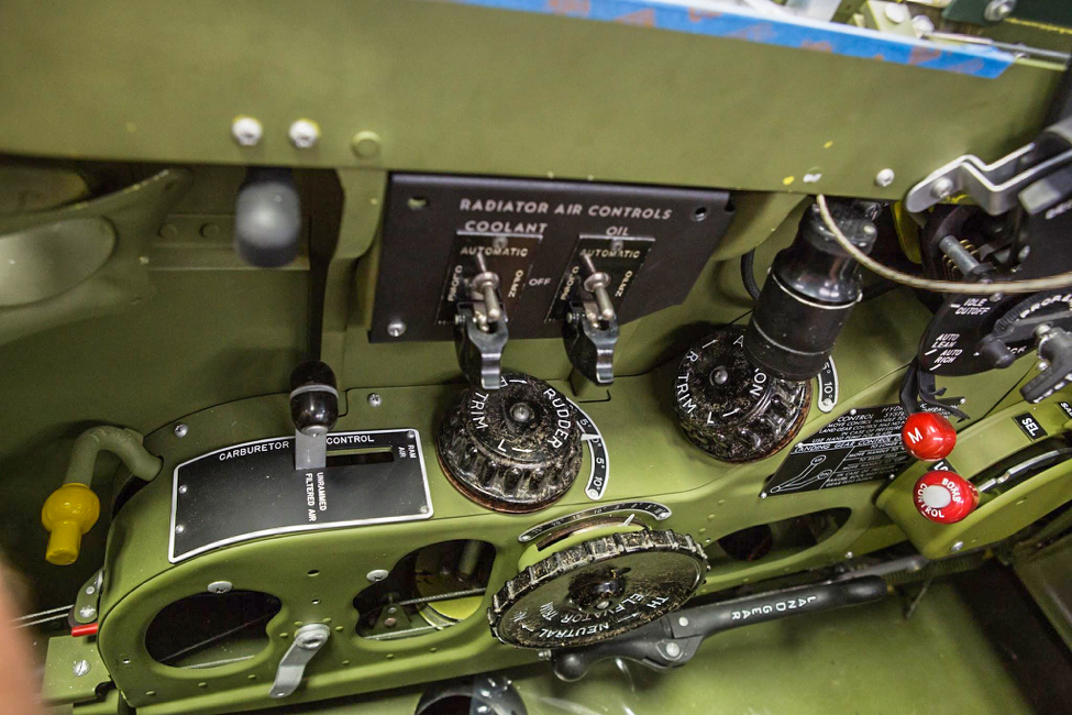
The trim console is on the left side of the cockpit. (photo via AirCorps Aviation)
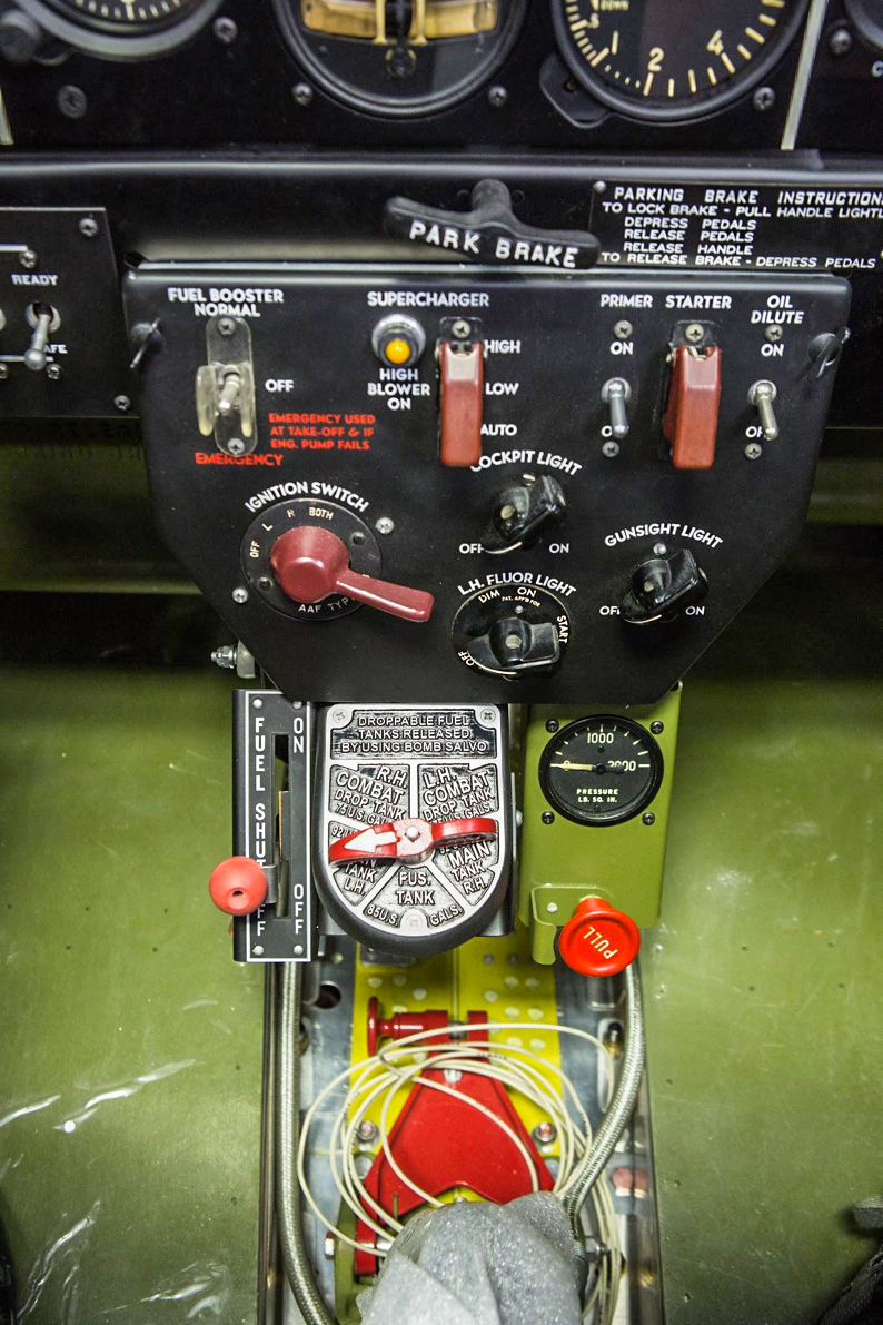
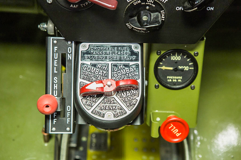
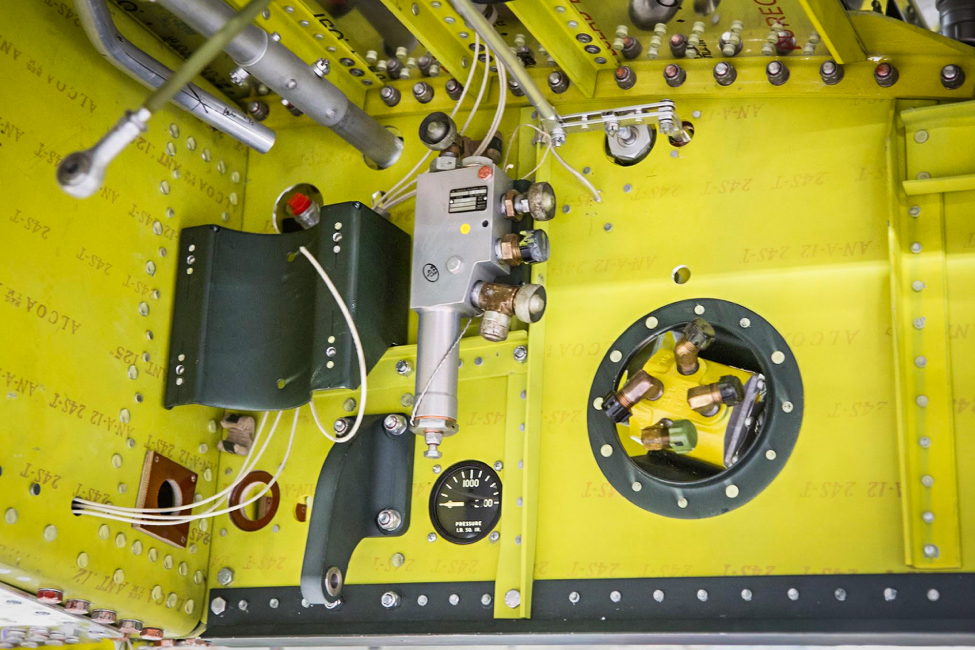
Here we have the pilot’s main switch box. (photo via AirCorps Aviation)
A closer shot shows detail of the fuel shut off, fuel selector, hydraulic pressure gauge, and the red pull knob that would dump hydraulic pressure when pulled. (photo via AirCorps Aviation)
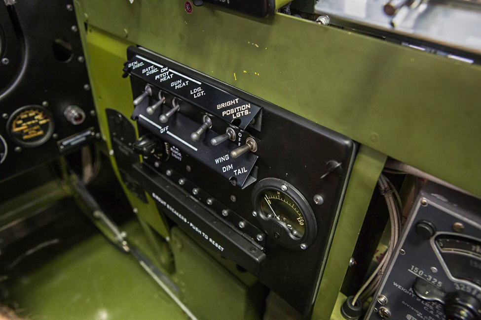
The right side switch box labels show clearly in this photo. (photo via AirCorps Aviation)
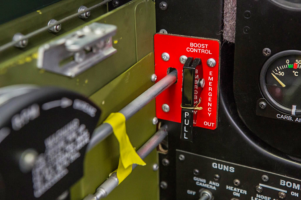
The lever labeled “pull” is the war emergency power control. It is wired down, as they were in WWII, because use of the war emergency boost level would normally call for an engine replacement, so it was intended as a life-saving last resort. The pilot had to pull hard enough to break the wire, so accidental use was prevented. (photo via AirCorps Aviation)
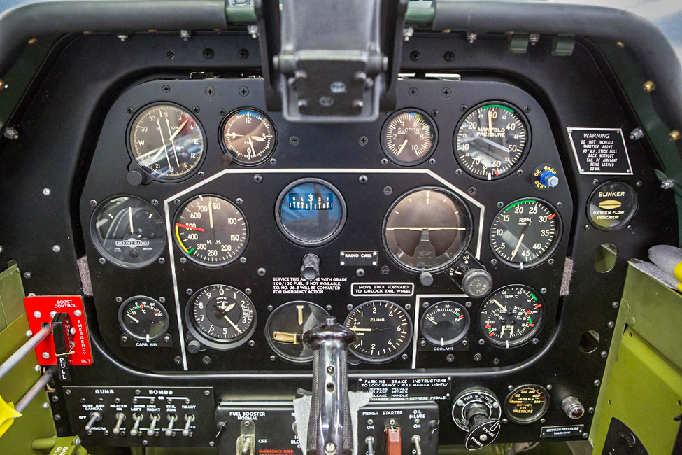
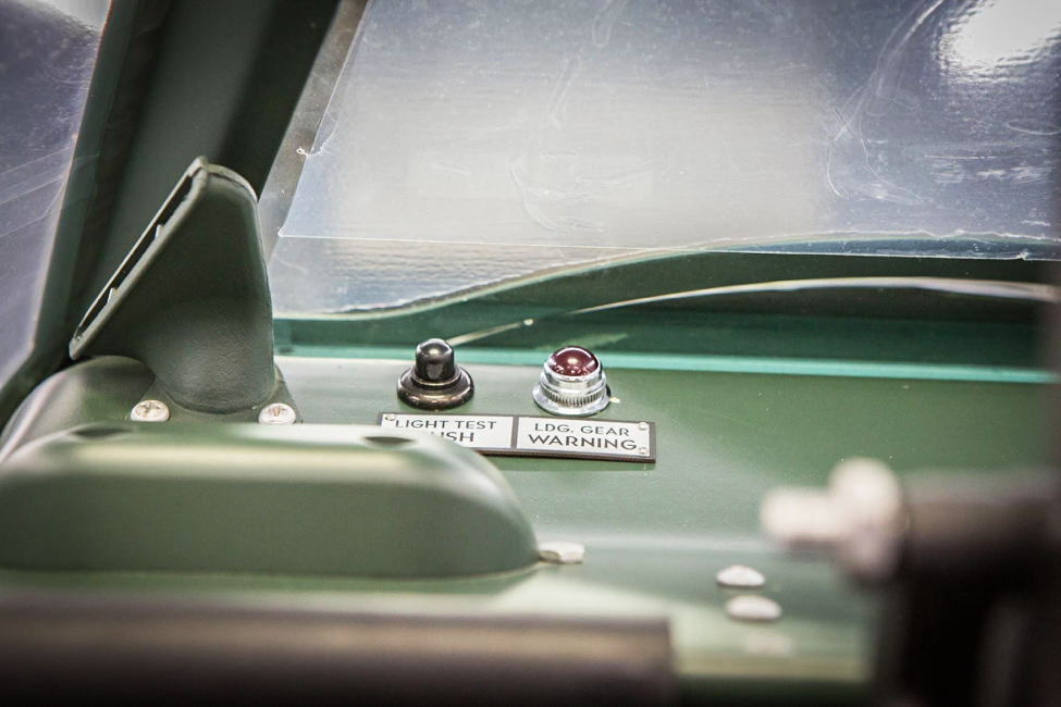
The instrument panel is complete in this view except for the oxygen regulator. (photo via AirCorps Aviation)
The red light is the landing gear warning light and the push button is used to test the light. (photo via AirCorps Aviation)
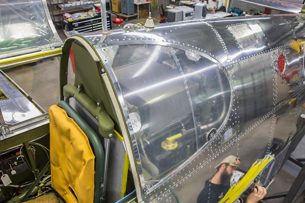
The pilot enters the cockpit from the left. The greenhouse canopy of a P-51C is hinged on the left and top; the ride side is fixed. (photo via AirCorps Aviation)
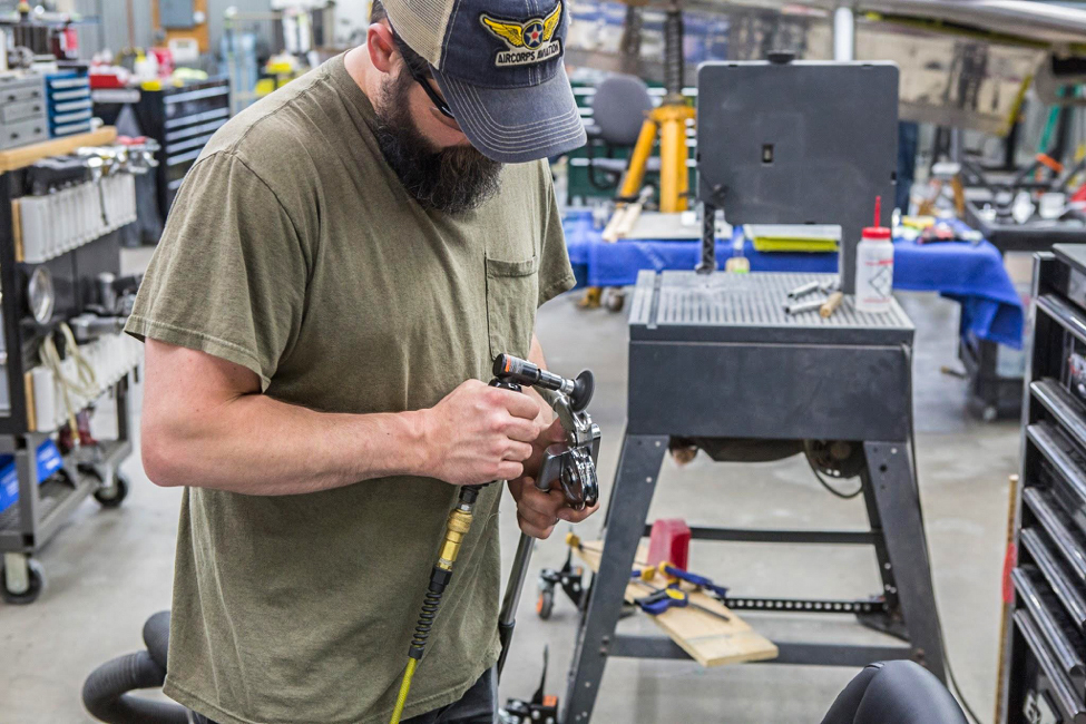
Randy is smoothing the tubing bender that he will use for Lope’s Hope’s various tubing runs. (photo via AirCorps Aviation)
Fairings
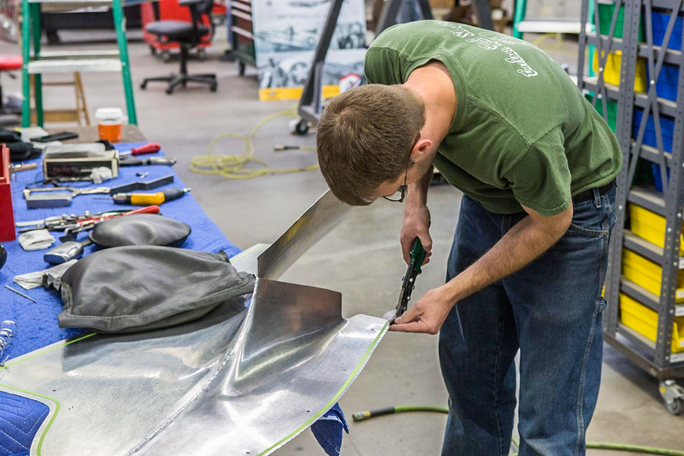
Randy Carlson of Carlson Metal Shaping helped us out on the various fillets. He is a specialist in the complex forming of these tightly compound-curved pieces.
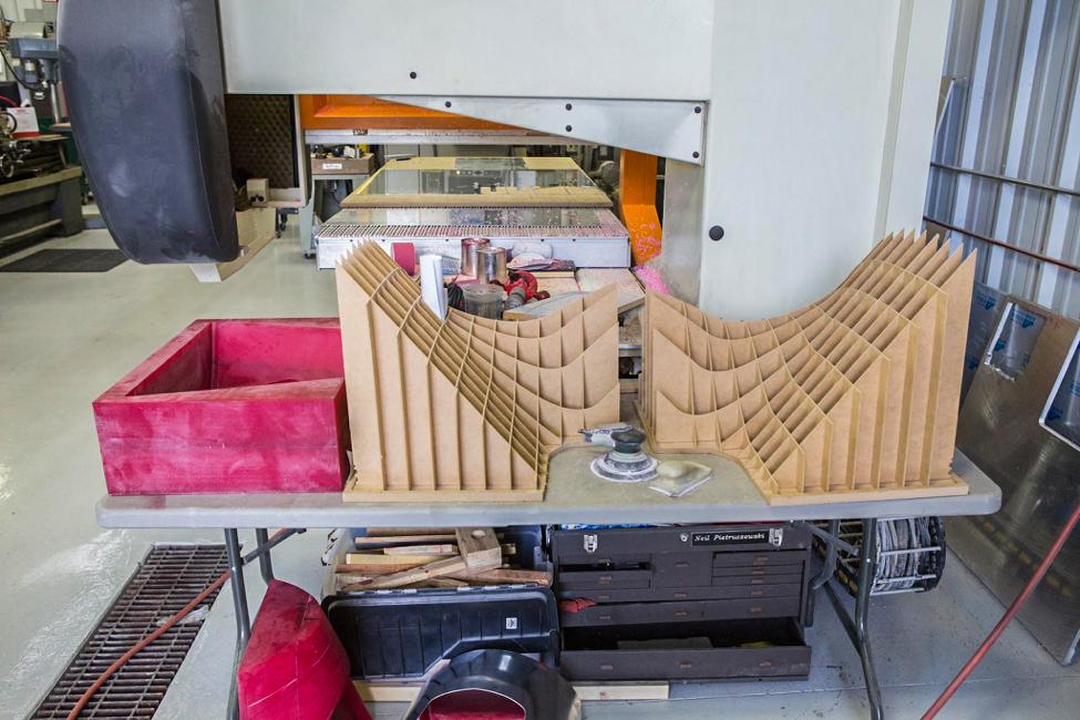
Bucks are forms created in an “egg crate” fashion and used to develop the three dimensional shape of the fillets. (photo via AirCorps Aviation)
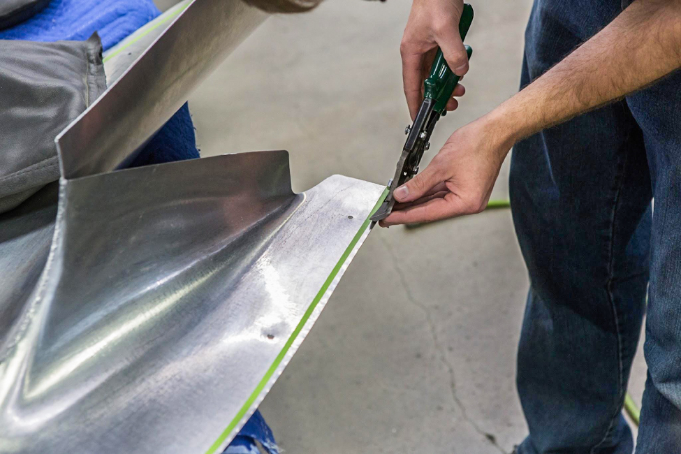
Randy carefully trims a fillet piece that smooths the wing trailing-edge-to-fuselage juncture. (photo via AirCorps Aviation)
This view gives us more detail of the trimming operation. (photo via AirCorps Aviation)
Randy checks the fit, trims, and repeats many times to get the perfect final wing fillet. (photo via AirCorps Aviation)
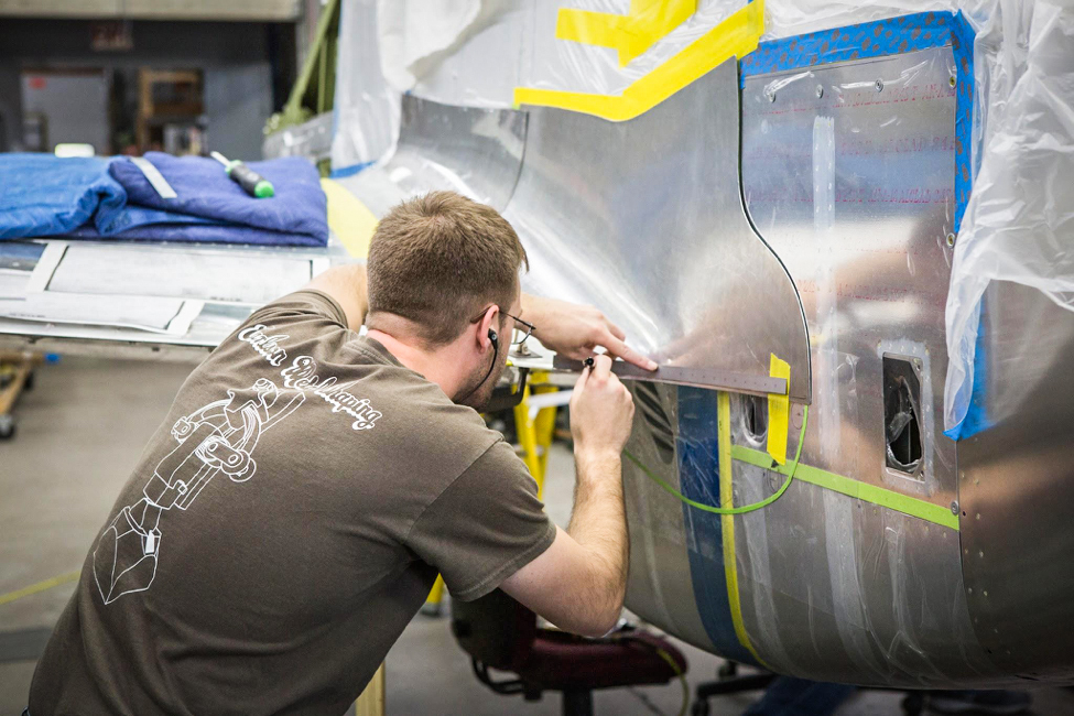
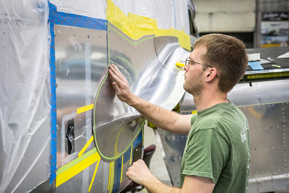
Randy tapes the final outer contour, before trimming the fillet. (photo via AirCorps Aviation)
The process of taping for the final trim is one where accuracy is critical. A mistake could mean starting over. (photo via AirCorps Aviation)
Gun Bays
Without guns, some say it isn’t a fighter, so work on the replica gun installations was an important part of this month’s restoration effort.
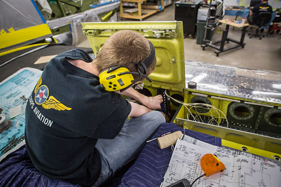
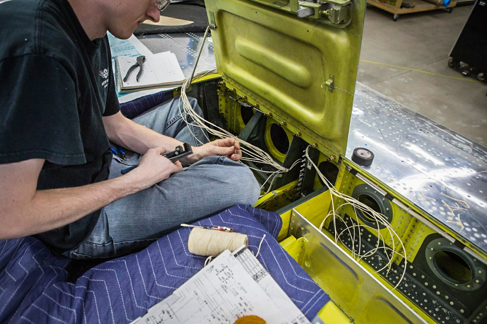
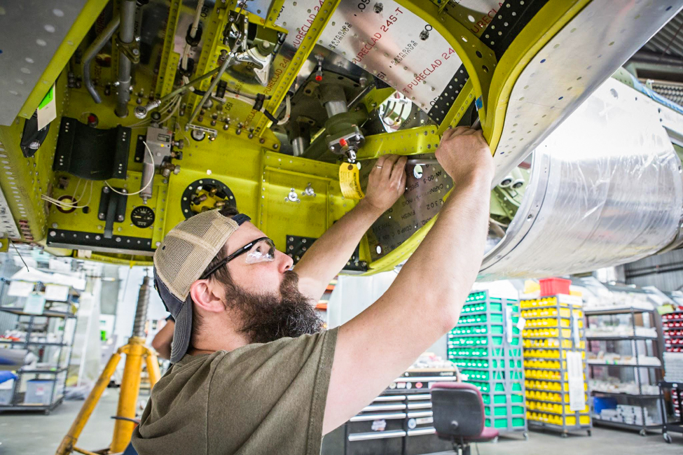
Aaron runs wires in the gun bay area. (photo via AirCorps Aviation)
Aaron works to connect the various harnesses to the terminal strip visible ahead of his knee. (photo via AirCorps Aviation)
The main landing gear harness comes up from the landing gear well to the strip. The wing lighting, bomb release, and drop tank harnesses extend outward from the terminal strip.
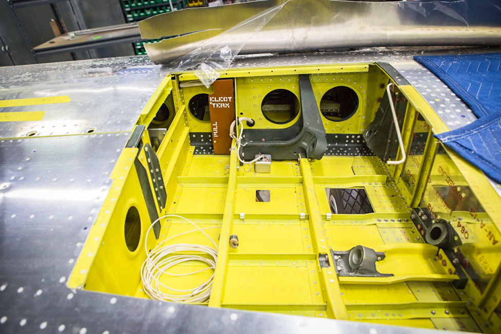
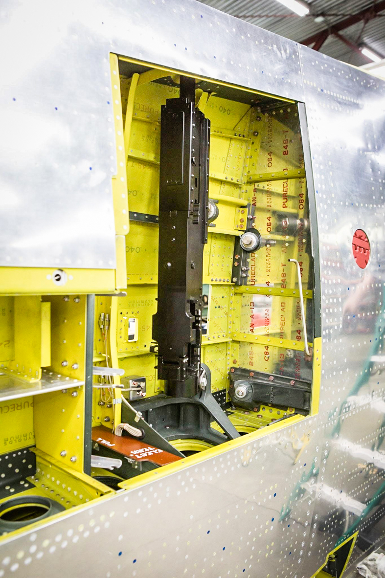
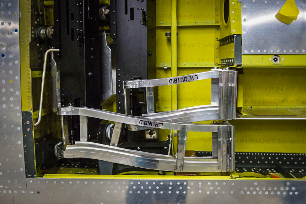
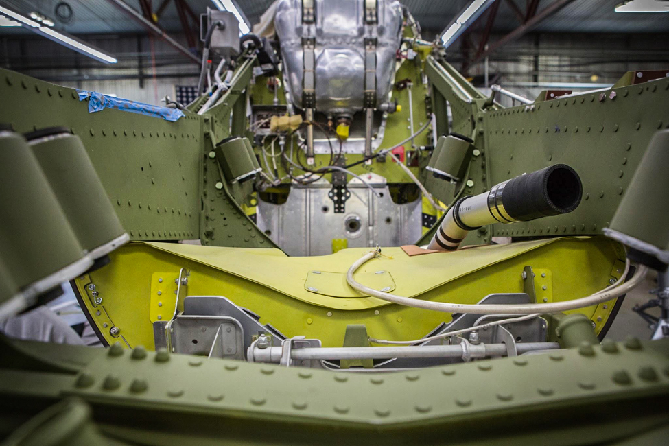
In the P-51C gun bay, we can see the tilt of the one set of gun mounts that has already been installed. (photo via AirCorps Aviation)
The currently installed set of gun mounts in the picture above are the darker green painted parts lined up with the large hole in the main spar on the right, which the gun will pass through. The small, nearly square hole in the bottom of the gun bay is where the links from the gun belts drop after firing. The larger one is where a chute attaches to guide the spent brass cartridge cases out.
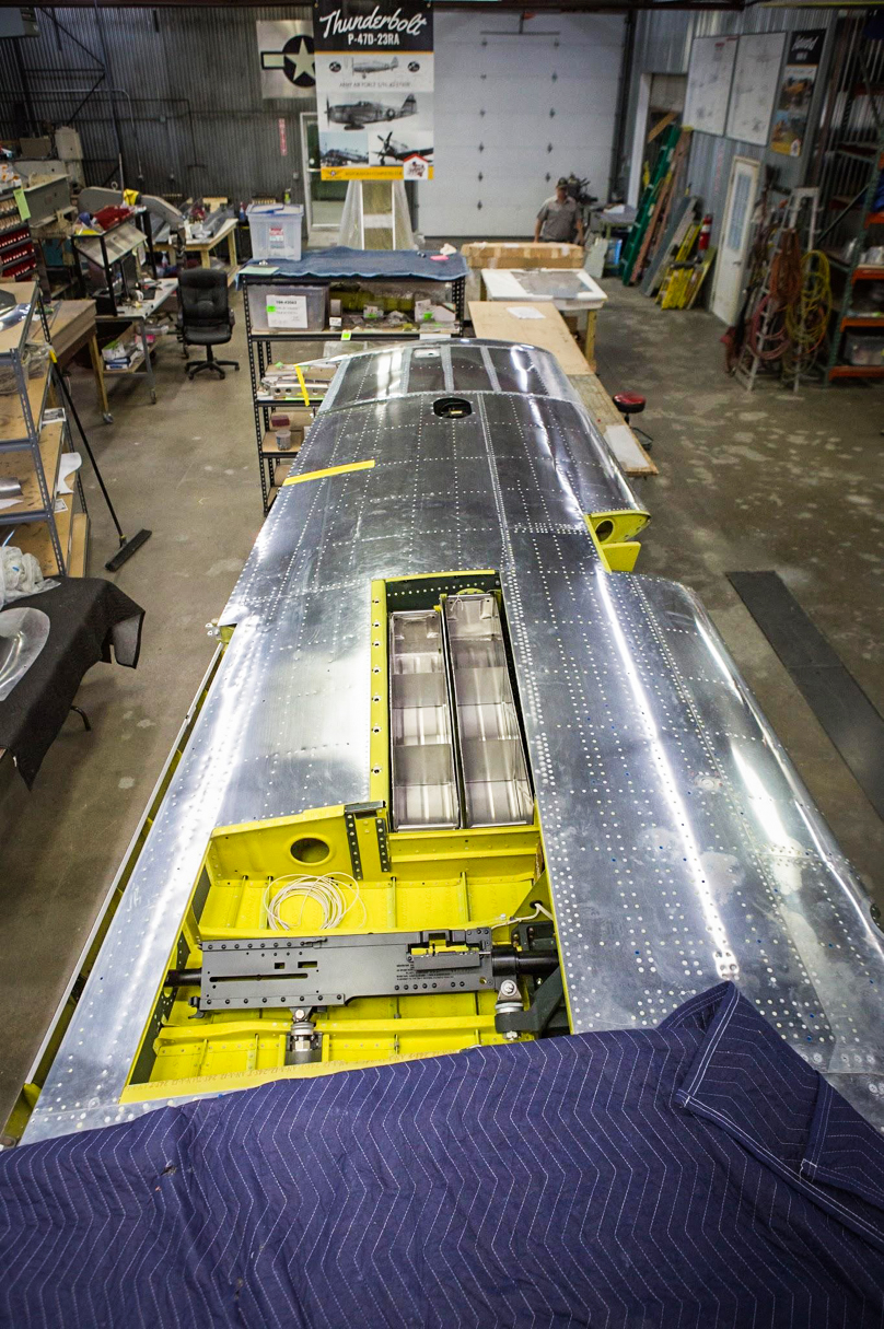
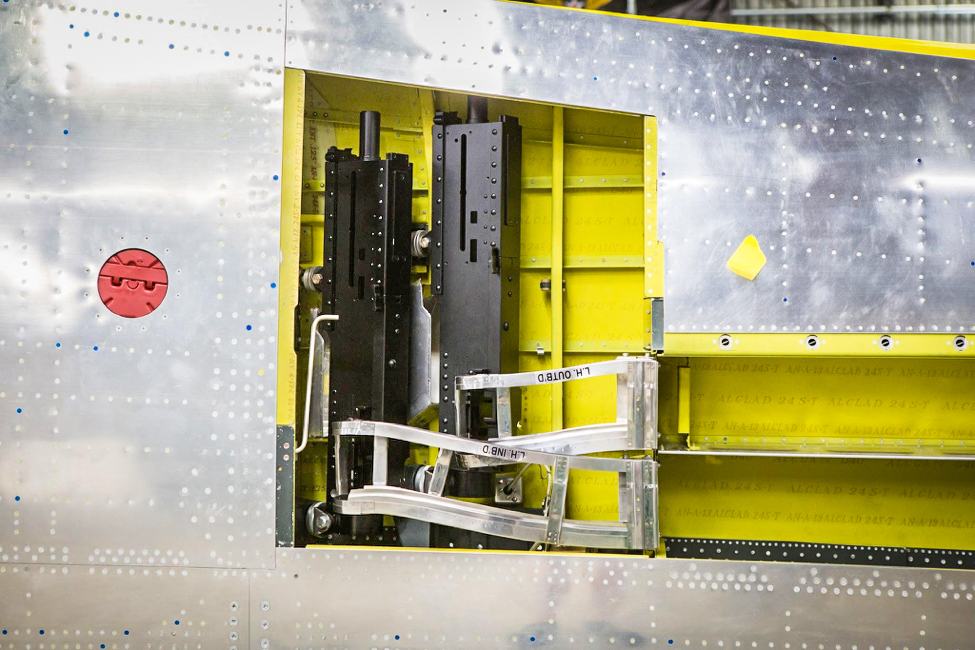
The Browning M-2 .50 caliber replica has been mounted in this image. (photo via AirCorps Aviation)
Two ammunition chutes lead to the gun bay in each wing of a C model. One replica M-2 is already installed. (photo via AirCorps Aviation)
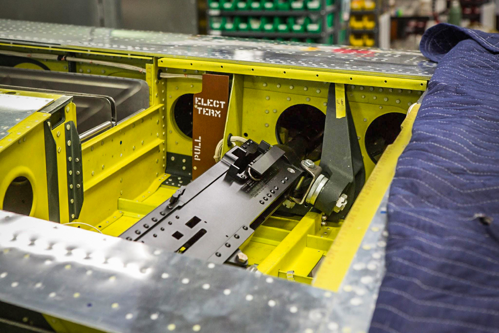
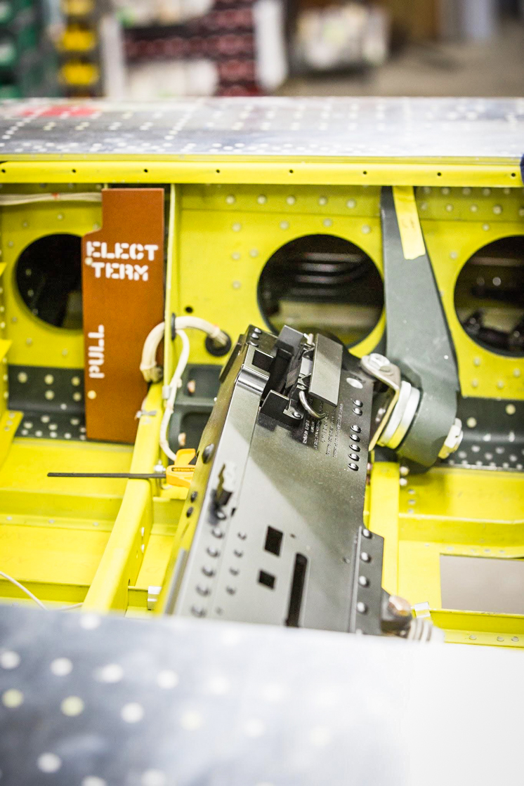
A view from the trailing edge shows more detail of the M-2 installation. (photo via AirCorps Aviation)
Ammunition belts come into the Browning’s receiver through the forward port in this image. (photo via AirCorps Aviation)
The sharp bend necessary to enter the receiver port led to some jamming issues in Mustangs during high “G” maneuvers. Donald Lopez lost a good chance for a victory over an enemy fighter when he encountered this problem on his 100th mission.
Both guns are installed with the guide chute assemblies in place. (photo via AirCorps Aviation)
A further back view displays the location for the guns in the wing. The red item on the left is a wing fuel tank cap. (photo via AirCorps Aviation)
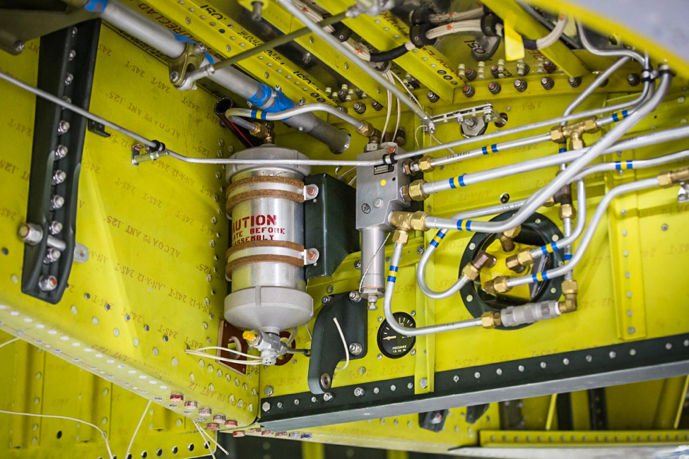
Wheel Wells
Plumbing for hydraulics and running electrical wiring went along with the installation of various system components in the gear wells.
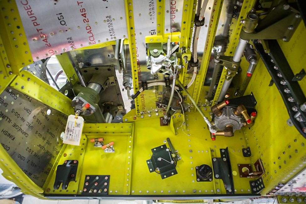
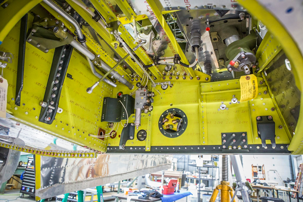
The whole wheel well shows clearly in this photo. (photo via AirCorps Aviation)
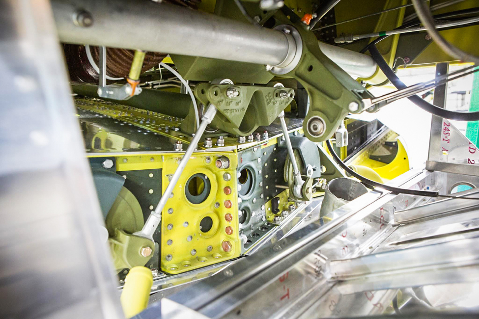
This is one of the main gear hydraulic actuators mounted to the front of the forward spar. (photo via AirCorps Aviation)
The hook-like part is the main gear uplock latch. (photo via AirCorps Aviation)
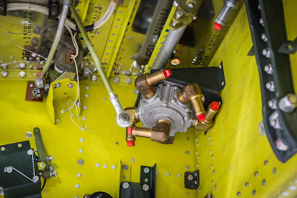
The fuel selector valve mounts inside the wheel well. The lower brass elbow is the outlet that delivers fuel to the engine. The other five serve as inlets from two wing tanks, two drop tanks, and the fuselage tank. (photo via AirCorps Aviation)
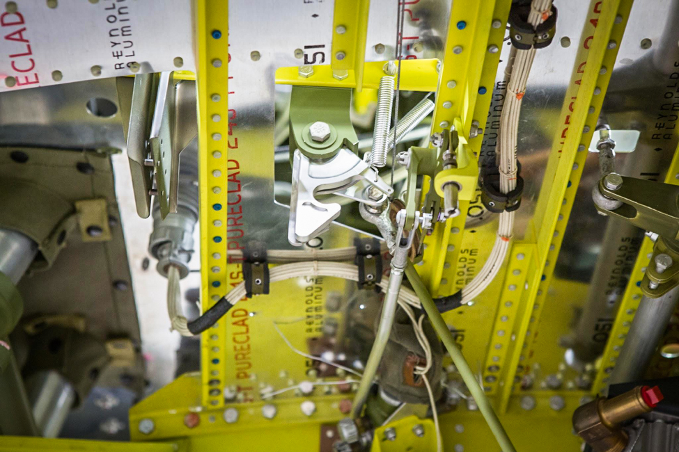
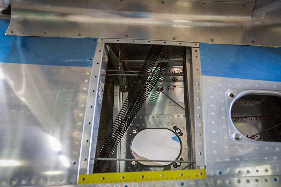
These springs hold the tail wheel straight as it retracts. (photo via AirCorps Aviation)
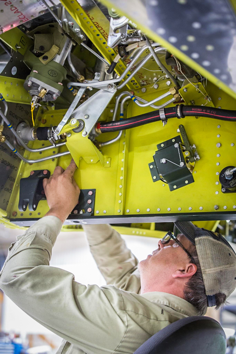
Robb is installing the bracket for the fuel shut-off linkage. (photo via AirCorps Aviation)
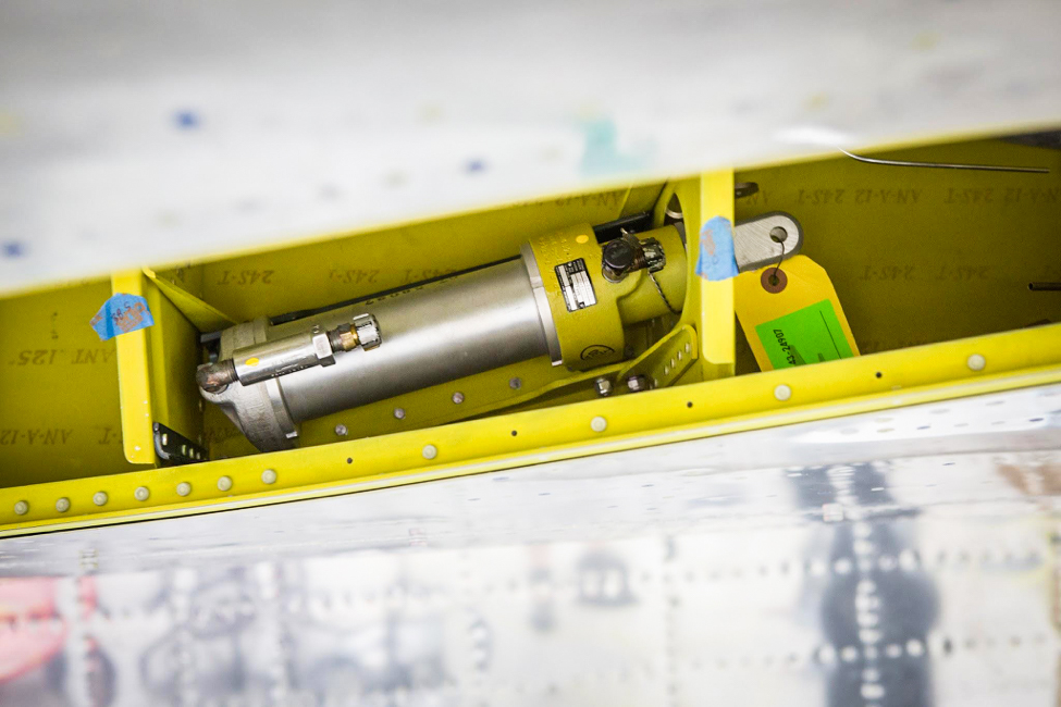
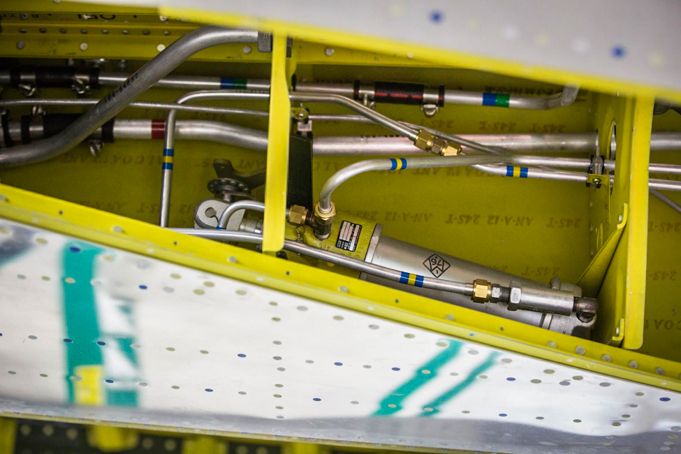
The hydraulic accumulator (cylinder at image center) stores pressurized hydraulic fluid for the landing gear retraction system. (photo via AirCorps Aviation)
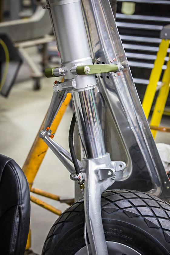
The main landing gear scissors and fork show up well in this image. (photo via AirCorps Aviation)
Randy installs a drop tank pressurization line. (photo via AirCorps Aviation)
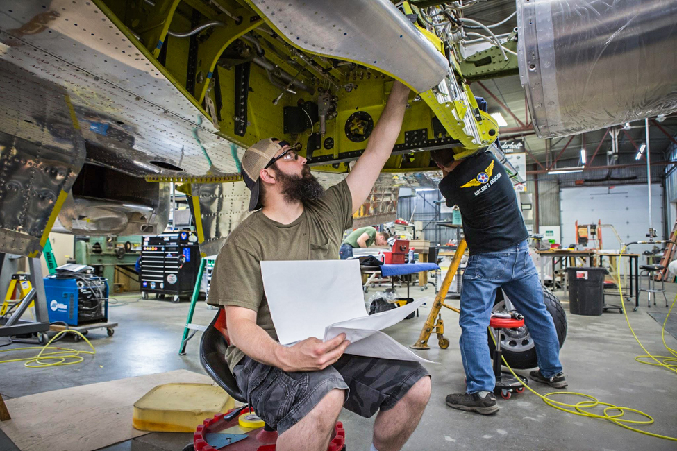
Randy checks the engineering drawings as he looks over gear well installations. (photo via AirCorps Aviation)
The silver-colored component with the black data plate is the hydraulic valve for the landing gear. (photo via AirCorps Aviation)
Here we have a good view showing most of a wheel well. The tagged part is the gear door hydraulic actuator. (photo via AirCorps Aviation)
The gear actuator in the other wing has been hooked up to its hydraulic lines. (photo via AirCorps Aviation)
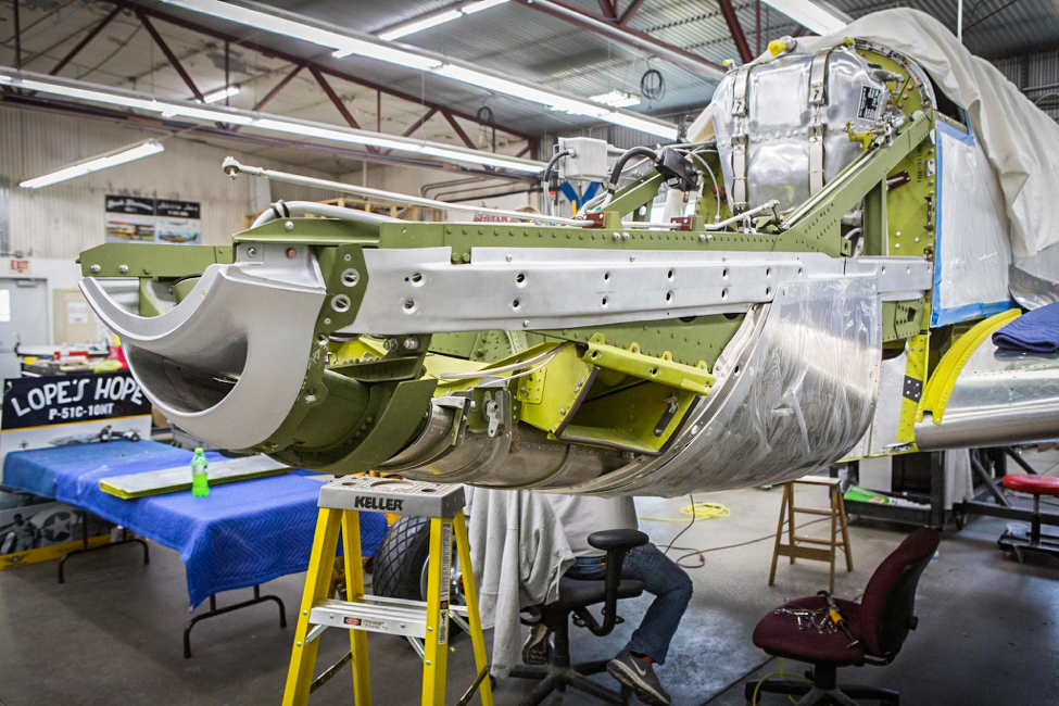
Firewall Forward
The oil tank is on the firewall and the engine mount assemblies support the “smile”, lower rear cowl section, and the air cleaner boxes. (photo via AirCorps Aviation)
A front view of the engine mount area shows both the forward and rear engine mounts with their rubber inserts. (photo via AirCorps Aviation)
Control Systems
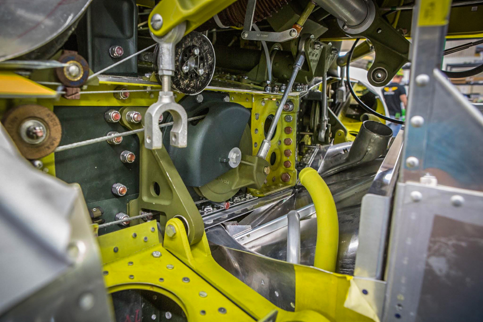
The pulley near the middle of the image is the aileron control pulley for the left wing. (photo via AirCorps Aviation)
A tighter view shows details of the linkage between the control stick torque tube and the aileron pulleys. (photo via AirCorps Aviation)
The Engine Runs!
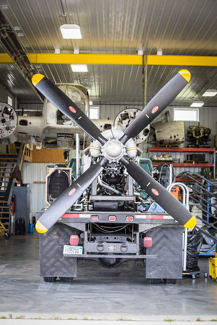
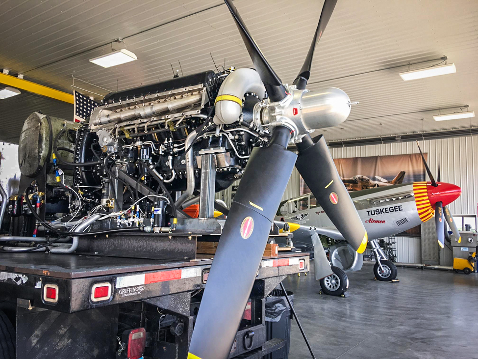
Out at the hangar, the V-1650-7 Merlin has been mounted on a truck and test run. The truck belongs to Pat Harker and this is the first time we have had the luxury of running the engine before installing it permanently in a P-51.
The V-1650-7 on the engine-test truck. (photo via AirCorps Aviation)
We tested the engine shortly after taking this picture. The Merlin ran beautifully! (photo via AirCorps Aviation)
Paint
The painting process is one of the last steps required before we can send the fuselage and wing out to our hangar for final assembly.
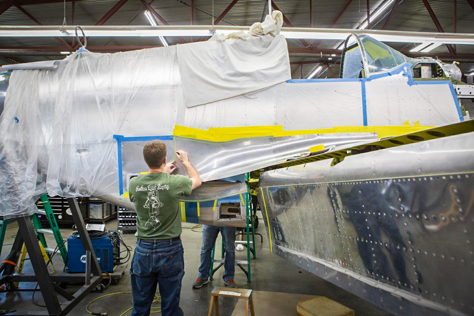
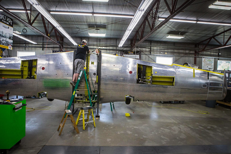
Wing de-mating prior to painting. (photo via AirCorps Aviation)
Before painting, the wing and fuselage need to be separated one final time.
Here, the fuselage is shown following separation from the wing. It is mounted to a rolling fixture. (photo via AirCorps Aviation)
Forward view of the fuselage on the rolling fixture. (photo via AirCorps Aviation)
The wing also has a rolling fixture so we can move it easily into the paint booth. (photo via AirCorps Aviation)
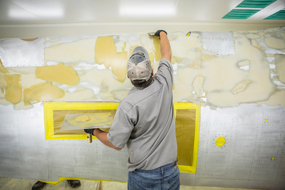
Robb applying “Aerodynamic Smoothing Compound”. (photo via AirCorps Aviation)
‘Aerodynamic Smoothing Compound’ was used to help create the smooth surface for the laminar flow airfoil by filling in rivets and other irregularities. Laminar flow was never completely achieved with the P-51, despite the compound and painting that followed.
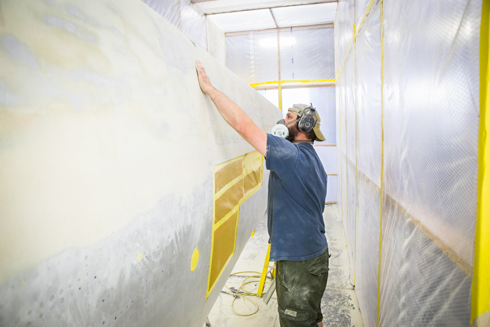
Randy is seen here during the sanding process. It is very time consuming work! (photo via AirCorps Aviation)
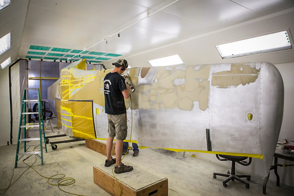
More sanding is taking place here to get the wings ready for their silver paint and markings. (photo via AirCorps Aviation)
And that is all for this latest restoration update from AirCorps Aviation. Many thanks to Chuck Cravens for writing the article, and to AirCorps Aviation for their support! We will be publishing more of these pieces in the future, so tune in each month and let us know what you think. We know everyone at AirCorps Aviation would love to hear from you too!


The wing looks so smooth
no bondo would go on a ww2 plane I would own .